This jammer, code named Broadloom I, was the first to use one of the techniques feverishly explored in the middle of the war to raise power outputs at VHF and UHF frequencies. Faced with the inability to use conventional triodes and tetrodes at power levels of more than 20 or 30 watts output, this transmitter was designed to use an early 1930s development - a split anode magnetron - to obtain 150W CW output from about 140 MHz to almost 800 MHz. They used two different tubes to cover this frequency range , along with an impressive amount of hardware devoted to the care and feeding of this simple(!) one tube transmitter. These tubes differed from the more familiar cavity magnetrons used for pulse radar work in that they used an external resonant LC circuit, sometimes called a tank, to provide an impressive tuning range.
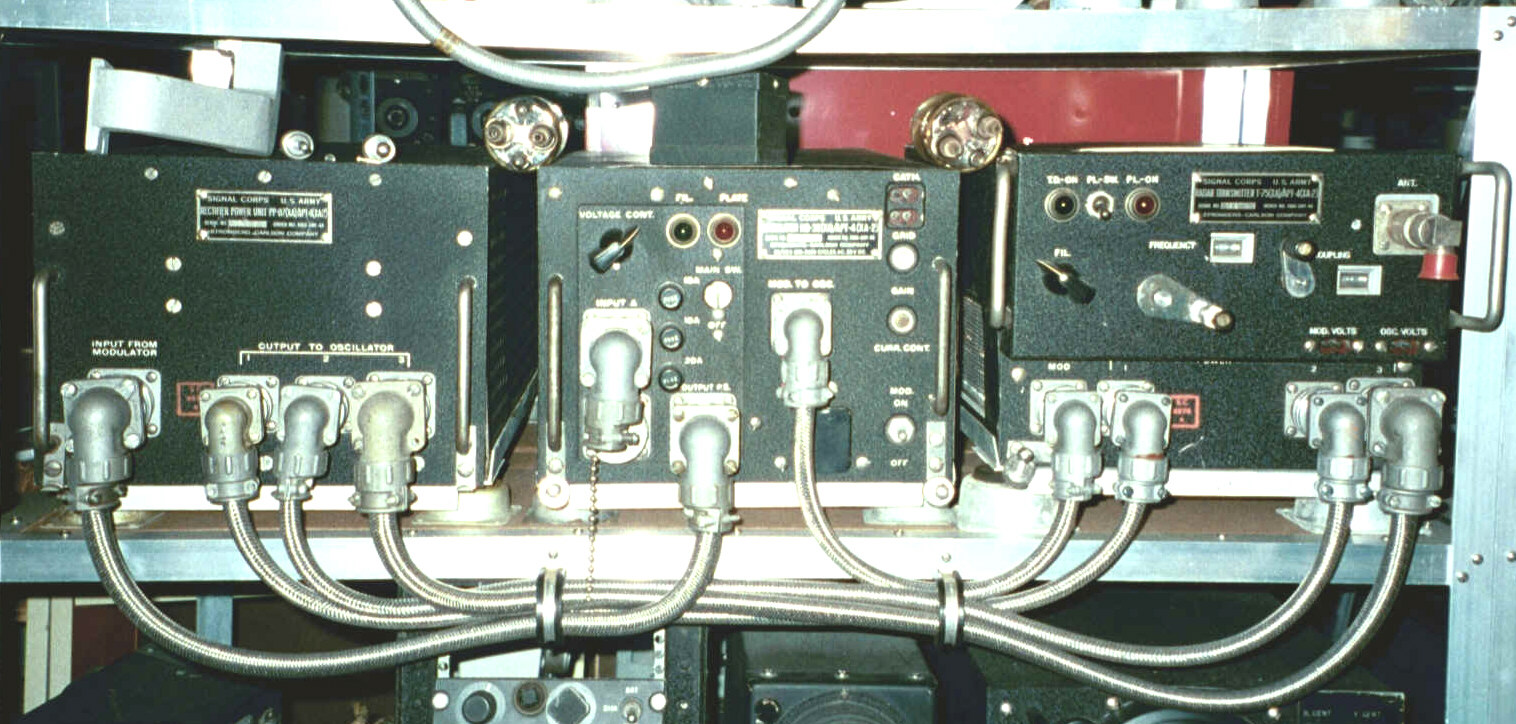
Composed of three separate packages - left to right a power supply, an AM modulator using a pair of 813 PA tubes, and the transmitter - this prototype set by Stromberg Carlson had a production run of only 100 sets.
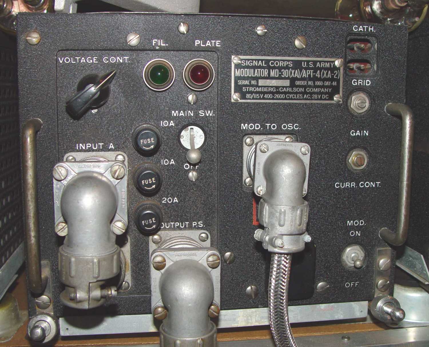
Closeup of Modulator
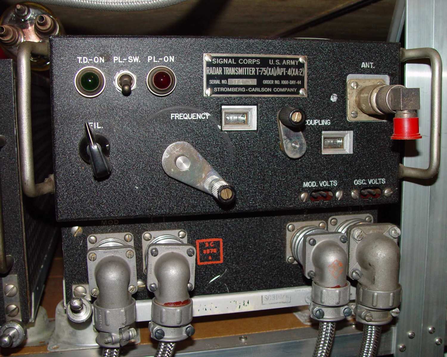
Closeup of Transmitter
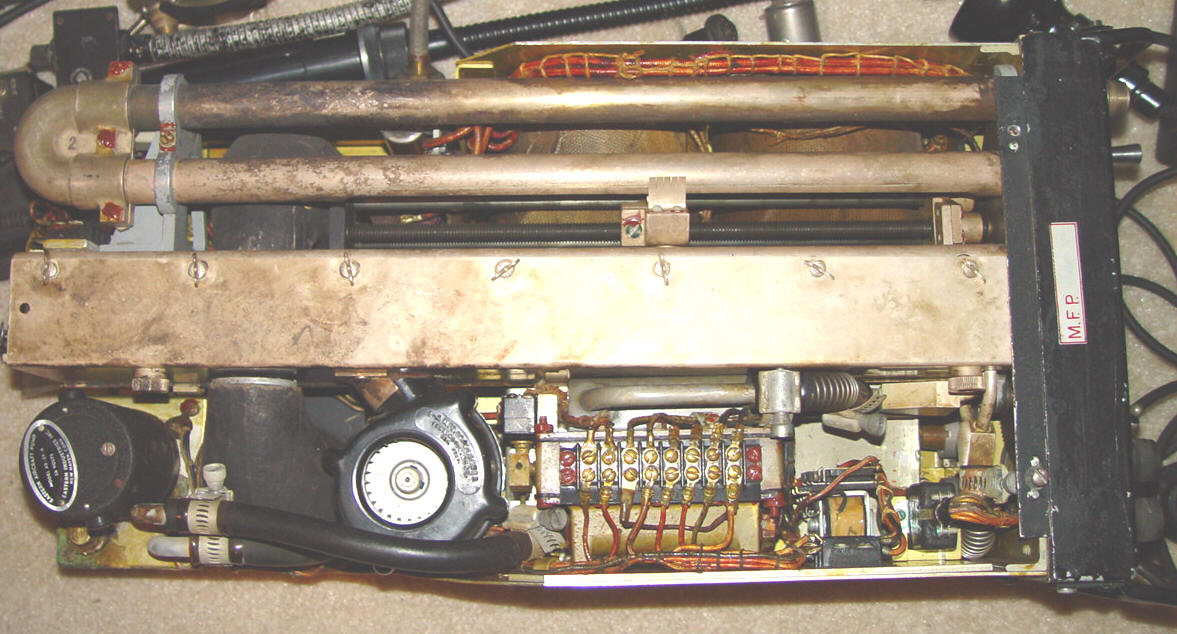
GE was selected to manufacture the final product, and there are small changes between this rare example and the later GE set that had an initial production of 2,092 sets. Below is a photo of the interior of the GE transmitter, showing the long tuning cavity and coaxial line stretcher "trombone" used to get the frequency down to its surprising low end of 2 meters.
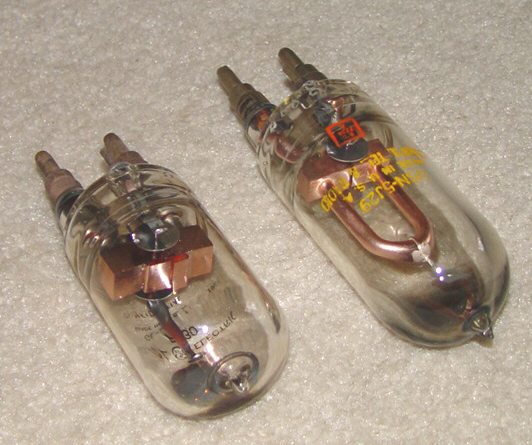
There was a serious filament "back heating" problem that plagued the early developers (analogous to thermal runaway in a transistor circuit), Initial operation with the split anode tube ran into an impractically short lifetime of less than 30 hours for the tube. It seems that you have essentially a miniature cyclotron at work in the tube, and especially at frequencies below about 150MHz, electron leakage from the anodes bombarding the glass seals was causing the early failure. Eventually, the simple addition of washers and nuts above the seals deflected the electrons from the seals enough to make the tubes last ten times as long. Even so, there is an impressive amount of heat to be carried away from an operating tube, and this package is filled with electric motors to accomplish that task - three blowers (two to blow air through the glycol cooled radiator used to keep the tube temperature down), as well as a coolant pump at lower left. The recirculation method depended on which of the two magnetrons was used. The lower frequency magnetron at left below required coaxial brass tubes to circulate pure glycol deep into each anode of the magnetron, recovering the hot fluid coming back out in the outer brass tube. The higher frequency tube had a continuous loop through the tube, so circulation wasn't quite so difficult a problem and could recover more heat in operation. Changing magnetron types on the Stromberg Carlson prototype required turning a valve 90 degrees, while the later GE set accomplished the same thing through the tube attachments. Below is a closeup of both tubes - a 5J30 on the left and 5J29 on the right.